It’s 2 a.m. An ISP engineer logs into a remote switch and sees that the 10G uplink that was working perfectly yesterday is suddenly Link Down. Replace the module? Swap the fiber? Reboot the switch? Most engineers start with the most expensive guess and work backwards from there.
The truth is, SFP modules stop working for reasons that are usually simpler — or more hidden — than you think. This article skips the textbook theory and goes straight to the eight real-world reasons SFP modules fail in the field, ranked from most to least common, with practical fixes for each one.
The last reason on this list is the one that 90% of engineers overlook. But it explains every “mysteriously fixed itself” failure you’ve ever seen — and once you understand it, you’ll spot trouble months before it causes an outage.
Reason 1 — The Module Isn’t Fully Seated
This is the single most common cause of SFP failures, and also the most underestimated. Roughly 30% of “dead module” tickets turn out to be modules that simply aren’t inserted properly.
Why “It Looks Inserted” Isn’t Enough
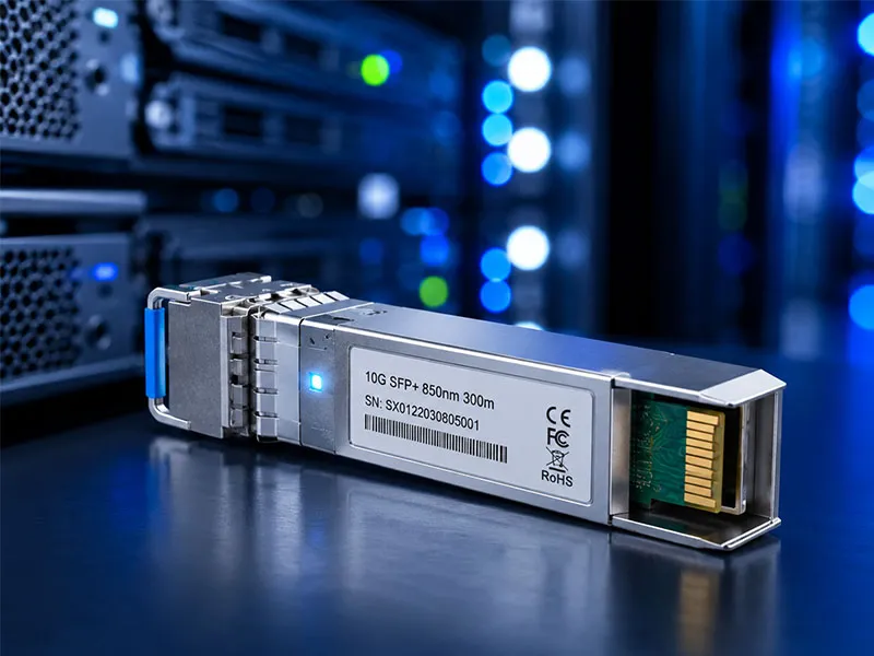
An SFP module looks fully installed long before it actually is. The optical port and the bail latch can be flush with the front panel while the electrical pins inside the cage have only made partial contact. The result is intermittent recognition, repeated link flapping, or a port that simply refuses to come up.
A properly seated SFP must satisfy three conditions: the module is pushed in until you hear an audible click, the bail latch is fully rotated to the locked position, and the port LED responds within a few seconds of insertion. If any of these are missing, the module is not seated correctly — no matter how it looks from the front.
How to Re-Seat Properly
Pull the module out completely. Inspect the gold-finger contacts at the rear of the module for dust, oxidation, or any visible damage. Blow out the cage with compressed air to clear any debris that may have accumulated inside. Reinsert the module firmly until you hear the click, then push the bail latch fully down to lock it in place.
In dense rack deployments, neighboring modules can put pressure on each other and cause one to back out slightly over time, especially after temperature cycling. If you have a port that intermittently drops, re-seating is always the first thing to try before assuming the module has failed.
Quick Diagnostic Commands
Use these commands to verify the switch has actually recognized the module:
- Cisco IOS / IOS-XE: show interface transceiver detail
- Huawei VRP: display transceiver verbose
- MikroTik RouterOS: /interface ethernet monitor [find name=sfp-port]
- Juniper Junos: show interfaces diagnostics optics
If the module is recognized but the link is down, the seating is fine and the problem lies elsewhere. If the module isn’t recognized at all, re-seat first before doing anything else.
Reason 2 — Single-Mode vs Multi-Mode Fiber Mismatch
This is the most expensive mistake in SFP deployment, because the module appears to work — it gets detected, DDM may even show TX power — but the link never comes up properly. Engineers waste hours blaming the modules, the switches, or the patch panel before realizing the fiber type is wrong.
The Yellow vs Orange Cable Trap
Single-mode fiber (SMF) is almost always sheathed in a yellow jacket. Multi-mode fiber (MMF) comes in orange (OM1/OM2), aqua (OM3/OM4), or lime green (OM5). This color coding exists for exactly this reason — to prevent mismatches in the field. But in busy data centers and crowded fiber distribution boxes, techs frequently grab the closest patch cord without verifying.
A single-mode SFP plugged into multi-mode fiber will see catastrophic signal scattering inside the wider fiber core. A multi-mode SFP on single-mode fiber will see severely reduced TX coupling efficiency. Either way, the link refuses to establish.
What Happens When You Mix Them
The symptom is distinct: the module is detected by the switch, DDM may report normal TX power, but RX power on the far end shows extreme loss — often beyond -30 dBm. The link either stays down completely or comes up briefly and drops within seconds.
Don’t waste time troubleshooting CLI configurations or replacing the module. If the link won’t come up cleanly and RX power is anomalously low, suspect the fiber type first.
How to Verify Fiber Type Before Plugging In
Read the printed text on the cable jacket. Single-mode cables typically read “OS1” or “OS2” with a 9/125 µm specification. Multi-mode cables read “OM1” through “OM5” with 50/125 µm or 62.5/125 µm. The connector boot color is usually a secondary indicator: blue for single-mode UPC, green for single-mode APC, beige for multi-mode.
In production environments where labeling is unreliable, use an optical power meter on a known reference link to verify continuity and signal level. This takes thirty seconds and saves hours of guesswork.
Reason 3 — Wavelength Mismatch Between Both Ends
Even when both sides use the correct fiber type, the wavelengths must also match. This is where the rules get more nuanced, and where BiDi modules trip up even experienced engineers.
Why SFP Modules Must Match in Pairs
Standard duplex SFP modules use the same wavelength for both transmit and receive — typically 1310nm for short-to-medium reach single-mode applications, or 1550nm for long-reach. If one end of the link uses 1310nm and the other uses 1550nm, the receivers are tuned to detect a wavelength that isn’t being sent. The link will not establish.
Always treat both ends of a fiber link as a matched pair. If you replace the module on one side, you must verify the wavelength on the other side.
The BiDi Trap: Using Two Identical Modules
BiDi (Bi-Directional) SFP modules transmit and receive on a single fiber strand using two different wavelengths — typically 1310nm in one direction and 1490nm in the other. This means BiDi modules come in two types: an “A” type that transmits at 1310nm and receives at 1490nm, and a “B” type that does the opposite.
Using two identical BiDi modules on both ends is one of the most common deployment errors. Both modules try to transmit on the same wavelength and listen on a wavelength nothing is sending. The result: a fully detected pair of modules with a permanently dead link. Always verify that you have one Type A and one Type B for every BiDi pair.
How to Check Wavelength Without the Datasheet
Most SFP modules print their wavelength directly on the label — look for markings like “1310nm”, “1550nm”, or “TX1310/RX1490”. If the label is illegible or missing, query the module via DDM. The transceiver detail output on Cisco, Huawei, and Juniper all expose the operating wavelength in the diagnostic data.
Reason 4 — Dirty or Damaged Fiber End-Faces
This is the silent killer of high-speed links. A perfectly compatible, properly seated SFP module connected to the right fiber type will still fail if the fiber end-face is contaminated. And the higher your data rate, the less contamination it takes to cause problems.
How a Speck of Dust Kills a 10G Link
A single dust particle as small as 5 microns sitting on the fiber end-face can cause 2 to 3 dB of insertion loss. On a 1G link with comfortable optical budget, that might be tolerable. On a 10G or 25G link operating near the edge of its budget, it pushes RX power below sensitivity threshold and the link either flaps continuously or never comes up.
Higher data rates use more sensitive receivers and operate with tighter optical margins. What was acceptable contamination on a Gigabit link is catastrophic on a 10G+ link. As networks upgrade speeds, fiber cleanliness becomes non-negotiable.
The 60-Second Cleaning Routine
Use a one-click fiber cleaner cartridge — the kind used on LC, SC, and MPO connectors. These are inexpensive, fast, and consistently effective. As a backup, lint-free wipes saturated with 99% isopropyl alcohol work well for end-face cleaning, but they require more care to avoid leaving residue.
Always inspect the end-face with a fiber inspection scope before reconnecting. Never wipe the end-face with bare cloth, paper towels, or your fingers — this introduces contamination rather than removing it.
When to Replace the Fiber Patch Cord Entirely
If the inspection scope reveals visible scratches, chipping, or contamination that returns immediately after cleaning, the patch cord has reached the end of its useful life. Replace it. The same applies to cables with bent connector boots, kinked jackets, or any sign of mechanical damage. A $5 patch cord replacement is always cheaper than the labor cost of repeated troubleshooting.
Reason 5 — Exceeded Maximum Transmission Distance
This is a selection-stage error that masquerades as a hardware failure. The module isn’t broken — it’s simply being asked to do something it was never designed to do.
A 10km SFP Won’t Magically Reach 25km
The rated distance on an SFP module is not a soft suggestion. It’s a hard physical limit determined by transmit power, receiver sensitivity, and assumed fiber attenuation. A 10km LR module pushed to 15km or 20km will deliver intermittent links, severe packet loss, or no link at all — depending on the actual loss budget of the run.
How to Calculate Real-World Distance Budget
The optical link budget formula is straightforward:
Available margin = TX Power − Total Loss − RX Sensitivity
Total loss includes fiber attenuation (approximately 0.35 dB/km for single-mode fiber at 1310nm, or 0.22 dB/km at 1550nm), connector loss (0.5 dB per mated pair), splice loss (0.1 dB per fusion splice), and any patch panel insertion loss.
Always reserve at least 3 dB of safety margin above RX sensitivity threshold. This buffer absorbs aging, minor contamination, and small temperature variations without pushing the link into instability.
When to Upgrade to ER or ZR Modules
For links between 40km and 80km, choose ER (Extended Reach) or LR-40 modules. For 80–120km links, use ZR (Long Reach) modules with high-power output and high-sensitivity receivers. For ultra-long-haul runs beyond 120km, you’ll need CWDM or DWDM modules combined with optical amplifiers — a different deployment topology entirely.
Reason 6 — “Unsupported Transceiver” Error (Vendor Lock-In)
This is the failure mode that infuriates anyone who has tried to save money by sourcing third-party modules. The module is fully MSA-compliant, optically perfect, and yet the switch flatly refuses to use it.
Why Major Brands Block Third-Party SFPs
Cisco, Juniper, HPE, and a handful of other vendors embed proprietary identification codes in the EEPROM of their original modules. When the switch firmware reads this code on insertion, it cross-references it against an internal whitelist. Modules that fail this check are flagged as “Unsupported Transceiver” or “Invalid GBIC” — even when they are functionally identical to the OEM module.
This is a commercial decision, not a technical one. The switch has no actual problem with the module. It just refuses to talk to anything that doesn’t carry the right brand stamp.
The Workaround: MSA-Compliant Modules with Vendor-Specific Coding
A reputable third-party manufacturer can program the EEPROM to match the exact vendor code expected by Cisco, Huawei, Juniper, HPE, Arista, MikroTik, Ubiquiti, or other major brands. The module is then recognized as native by the switch firmware. This is fully MSA-compliant and is how serious enterprise customers source compatible optics at a fraction of OEM pricing.
Always confirm the vendor coding when you order third-party SFPs. A good supplier will ask which switch brand and model you’re deploying into, and code accordingly. A bad supplier will ship generic modules and leave you to deal with the rejection errors.
Cisco-Specific Override Commands (Use with Caution)
In lab or non-critical environments, Cisco IOS allows the switch to be told to ignore unsupported-transceiver warnings:
- service unsupported-transceiver
- no errdisable detect cause gbic-invalid
These commands force the switch to bring up unsupported modules, but they may void support contracts and they don’t disable identification logging. For production environments, the correct path is to source modules with proper vendor coding from the outset.
Reason 7 — Overheating and Thermal Shutdown
Heat is the enemy of every optical component. Modern high-speed SFPs generate significant heat in a small package, and when ambient conditions or rack airflow can’t keep up, the module simply shuts itself down to protect its laser.
Why SFP+ and Higher Speeds Run Hot
A 1G SFP draws roughly 1 watt. A 10G SFP+ draws 1.5 watts. A 25G SFP28 climbs to 2.5 watts, and 100G QSFP28 modules can hit 3.5 watts or more. In a 48-port switch fully loaded with high-speed modules, the cumulative thermal load is substantial. Without sufficient airflow, internal module temperatures climb past the operational threshold of around 70°C and the laser begins to lose stability.
Once a module crosses its thermal warning threshold (typically 75°C), the firmware reduces output power or shuts the laser down entirely to prevent permanent damage. The link goes down, the port logs a thermal event, and the engineer sees a “failed” module that is actually working as designed.
How to Check Module Temperature via DDM
DDM (Digital Diagnostic Monitoring) exposes real-time module temperature in the transceiver detail output. The normal operating range is 0°C to 70°C for commercial-grade modules. Anything above 70°C is a warning, and above 75°C is a serious problem.
On Cisco: show interface transceiver detail. On Huawei: display transceiver verbose. Look for the temperature field and compare against the alarm thresholds also reported in the same output.
Cooling Fixes That Actually Work
Improve front-to-back airflow in the rack and verify that hot aisle / cold aisle separation is intact. Reduce port density if possible — leaving alternate ports empty in a fully populated chassis can drop module temperatures by 5–10°C. Install supplementary rack cooling fans for switches in poorly ventilated locations.
For deployments in genuinely harsh environments — outdoor cabinets, industrial sites, telecom shelters with poor HVAC — choose industrial-grade SFPs rated for -40°C to +85°C operation. The price premium is small compared to the cost of repeated thermal failures in the field.
Reason 8 — The One Most Engineers Miss: Aging Optics and Silent Power Drift
This is the hidden killer behind every “intermittent” failure that defies all other troubleshooting. It explains the modules that “fail” suddenly after years of perfect service, and the random packet loss that everyone blames on the fiber, the switch, or the upstream provider — when the actual culprit is sitting in the transceiver cage.
Why SFP Modules Slowly Lose Power Over Time
The laser diode inside every optical SFP module degrades with age. Output power drops by 1 to 2 dB over the first 3 to 5 years of continuous operation, and accelerates after that. The link still appears “up” the entire time, but it operates closer and closer to its receive sensitivity floor with each passing year.
Eventually, environmental factors that the link used to absorb without complaint — minor temperature shifts, slight bend changes in the patch cord, microscopic contamination on the connector — push it over the edge intermittently. The link starts flapping. Packet loss appears. The engineer replaces the module and the problem disappears, with no obvious explanation. The module wasn’t broken. It was just at the end of its operational margin.
How to Spot Power Drift Before It Causes Outages
Monitor TX and RX optical power values via DDM regularly. Compare current readings against the original baseline captured when the module was first installed. A drop of more than 2 dB from baseline is an early warning sign — even if the link still appears to work normally.
Build this monitoring into your network management routine. Most modern NMS platforms can poll DDM data continuously and alert when readings drift outside threshold. Catching power drift early lets you replace modules during planned maintenance windows instead of during 2 a.m. outages.
Safe Optical Power Ranges to Remember
Each module type has a defined safe operating range. As a quick reference for the most common modules:
- 10G SFP+ SR (multi-mode, 300m): TX -7.3 to -1 dBm, RX -11.1 to -1 dBm
- 10G SFP+ LR (single-mode, 10km): TX -8.2 to +0.5 dBm, RX -14.4 to +0.5 dBm
- 10G SFP+ ER (single-mode, 40km): TX -4.7 to +4 dBm, RX -15.8 to -1 dBm
- 10G SFP+ ZR (single-mode, 80km): TX 0 to +4 dBm, RX -24 to -7 dBm
RX values approaching the lower end of these ranges indicate aging optics, increased fiber loss, or both. Replace proactively rather than reactively — the cost of a planned module swap is a fraction of the cost of an unplanned outage.
Why Quality Matters: MTBF and Component Selection
This is where module quality reveals itself most clearly. High-quality SFPs use premium DFB lasers, well-matched PIN photodiodes, and rigorously tested optical alignment — they maintain stable output power for 5 to 7 years of continuous operation. Budget modules built with low-grade components drift outside spec within 18 to 24 months.
The dirty secret of cheap optics is that they don’t fail catastrophically. They fail slowly, invisibly, over months. By the time the symptoms appear, the original purchase saving has been wiped out several times over by troubleshooting hours, replacement costs, and customer complaints. Reason #8 is exactly why investing in quality optics pays back over the long run.
How to Avoid These 8 Failures in the First Place
Most SFP failures are not random events. They are predictable outcomes of installation oversights, environmental conditions, and component quality. A small amount of discipline at the procurement and deployment stages eliminates the vast majority of field problems.
Choose MSA-Compliant Modules from a Direct Manufacturer
Source from manufacturers who control the entire production chain — chip-level integration, optical alignment, firmware coding, and final testing — rather than from resellers who simply rebrand someone else’s product. Direct manufacturing control eliminates the variability that causes most “mysterious” SFP failures.
Verify Compatibility Before Bulk Deployment
Always request a compatibility test report or sample units before placing volume orders. Confirm that the EEPROM coding matches your switch vendor — Cisco, Huawei, Juniper, HPE, Arista, MikroTik, Ubiquiti, or whatever platform you’re deploying into. A 30-minute compatibility test prevents 30 hours of post-deployment troubleshooting.
Build a Baseline DDM Record from Day One
Capture every module’s TX power, RX power, voltage, and temperature on first deployment, and store these readings in your network documentation. This baseline becomes your reference for detecting Reason #8 (silent power drift) months or years before it causes outages. Without a baseline, you can’t tell whether today’s reading is normal or already showing 2 dB of drift.
The SHENGWEI Difference: Why Our SFP Modules Stay Working
Most of the failure modes covered in this article come back to the same root cause: low-quality components, weak compatibility coding, or sourcing from suppliers who don’t actually manufacture what they sell. SHENGWEI is built differently.
As a direct manufacturer of fiber optical transceivers from 1.25G SFP through 10G SFP+, 25G SFP28, 40G/100G QSFP+/QSFP28, and 400G/800G QSFP-DD, we control the entire production process — from chip integration to optical alignment to final testing. The result is a product line engineered specifically to eliminate the failure modes you’ve just read about:
- Full MSA compliance with vendor-specific EEPROM coding for Cisco, Huawei, Juniper, HPE, Arista, MikroTik, and Ubiquiti — no “Unsupported Transceiver” surprises
- Premium DFB lasers and matched PIN photodiodes selected for industry-leading MTBF — power drift stays well below spec for 5+ years
- Full DDM/DOM support with calibrated optical power readings for proactive monitoring and early warning detection
- Rigorous interoperability testing with major OEM switches and carrier equipment, ensuring plug-and-play performance from day one
- Flexible OEM/ODM services including custom wavelengths, firmware customization, and private-label branding
- Stable global supply chain with managed component inventory and predictable lead times for projects of any volume
If you’re tired of debugging SFP failures that should never have happened in the first place, it might be time to change where you source your optics.
Need SFP modules that won’t quietly drift out of spec? Get a free sample and a full compatibility report — request a quote from SHENGWEI today.
Final Thoughts
Most SFP “failures” aren’t actually failures of the module itself. They are a combination of installation oversights, environmental conditions, and the slow decline of low-quality components — all of which are preventable with the right knowledge and the right supplier.
Knowing these eight reasons turns hours of guesswork into minutes of targeted diagnosis. Symptom appears → check the most likely cause first → confirm with DDM data → fix or replace. That’s the workflow every experienced network engineer eventually develops, and now you have it explicitly.
And if you make one change after reading this article, make it this: start your next deployment with quality MSA-compliant modules from a direct manufacturer, capture baseline DDM readings on day one, and monitor for drift over time. That single discipline eliminates roughly 70% of the failures from your network — quietly, invisibly, and permanently.