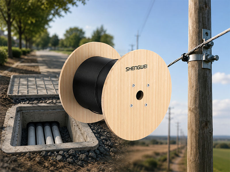
Outside plant fiber routes rarely stay in one environment for their entire length. A feeder line might leave a central office through underground duct, surface at a handhole near the edge of town, and continue the rest of the way on utility poles to reach a cluster of subscribers or a remote site. In rural and peri-urban builds across Africa, Southeast Asia, and Latin America, this duct-to-aerial transition is closer to the rule than the exception.
The cable selected for that route has to perform in both halves of the journey, or the network ends up with a transition splice closure at every junction, two separate spare-parts inventories, and a crew that has to be trained on two different cable structures instead of one. None of that is fatal on its own, but it adds cost and failure points to a network that is already running on a tight margin.
Why Duct and Aerial Segments Pull Cable Design in Different Directions
Duct-routed cable spends its life inside conduit, handholes, and manholes. The main risks there are crush load from soil settlement or duct congestion, moisture intrusion at handhole splice points, and rodent activity where ducts pass through agricultural land. A cable built for this environment typically carries some form of armor — steel tape, corrugated steel, or a similar barrier — wrapped around a water-blocked core.
Aerial cable faces a different set of stresses. Wind load, ice loading in some climates, thermal expansion and contraction across a pole span, and sustained tensile load from the span itself are the dominant concerns. Cable built for aerial use needs either a strength member capable of carrying that tensile load on its own, as in self-supporting designs, or enough tensile strength to be lashed safely to a steel messenger wire strung between poles.
A cable optimized purely for one environment usually compromises in the other. Lightweight self-supporting aerial cable has no armor and is not rated for duct placement. Heavily armored duct cable is often too rigid or too heavy to lash economically over long aerial spans. The practical middle ground, and the reason central tube, steel-wire-reinforced armored cable shows up so often in access and distribution network designs, is a construction that carries enough tensile strength for lashed aerial spans while keeping enough armor for duct and handhole exposure.
How Central Tube Steel-Wire Armored Construction Bridges Both Environments
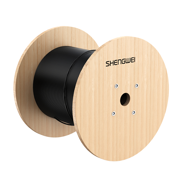
This cable family places all fibers in a single gel-filled central loose tube rather than stranding multiple tubes around a central member. That keeps the outer diameter small, typically in the 7–9 mm range for fiber counts up to 24 cores, which matters directly for duct fill ratio and for keeping pole-mounted weight down.
Two parallel phosphated steel wires run alongside the tube as the primary strength member, giving the cable enough long-term tensile rating, commonly around 600 N with short-term ratings closer to 1,500 N, to be lashed to a messenger wire across standard pole spans. A layer of steel tape wraps the core for crush resistance and rodent protection, typically rated for long-term crush loads around 300 N per 10 cm, and a UV-resistant HDPE jacket finishes the construction for sun and weather exposure. Bend radius requirements stay modest for a cable this size, generally 10 times the outer diameter static and 20 times dynamic, and most builds carry an operating range from around -40°C to +60°C, which covers both buried duct temperatures and direct sun exposure on an aerial span.
It is worth being precise about what “aerial-capable” means here: this is a lash-aerial cable, not a self-supporting one. It needs a separate steel messenger wire to carry the span load, with the cable lashed alongside it. That is a different installation method from all-dielectric self-supporting cable, known as ADSS, which carries its own span load with no external messenger and no metallic content at all. Confusing the two during route planning leads to either an under-engineered aerial span or an unnecessarily expensive duct deployment.
Where the Common Outdoor Cable Types Diverge
Three cable families cover most duct-and-aerial route designs, and each is built around a different priority.
Central tube steel-wire armored cable, the type described above, is built for compact size and dual-environment use at moderate fiber counts. It is the right fit when a single route segment moves between duct and lashed-aerial sections and the fiber count stays in the access-to-distribution range.
All-dielectric self-supporting cable removes metallic content entirely and relies on aramid yarn strength members to carry its own span weight between poles. That makes it the standard choice for long aerial spans run near or alongside medium- and high-voltage power lines, where any metallic sheath risks induced current. ADSS cannot go into a duct, and its spans need proper sag and tension engineering, but for pure aerial backbone runs it outperforms a lashed cable on span length and installation speed.
Double-armored stranded loose tube cable stacks multiple loose tubes around a central strength member and adds a second armor layer, usually a corrugated steel tape plus an additional protective layer. This is the structure built for high fiber count trunk and backbone routes, including direct burial without conduit in suitable soil. It is heavier and larger in diameter than central tube cable, and it is not intended for aerial lashing, but it is the right choice once fiber counts climb into the hundreds on a backbone segment.
| Cable Type | Strength Member | Installation Method | Typical Fiber Count | Best Suited For | Key Limitation |
|---|---|---|---|---|---|
| Central tube, steel-wire armored | Two parallel steel wires + steel tape | Duct, lash-aerial (messenger wire required) | 4–24 cores | Mixed duct-to-pole feeder and distribution segments | Not self-supporting; needs a messenger wire for aerial spans |
| All-dielectric self-supporting (ADSS) | Aramid yarn, no metallic content | Self-supporting aerial only | 12–144+ cores | Long pole spans near power lines, fast aerial backbone builds | Cannot be installed in duct; spans require sag/tension engineering |
| Double-armored stranded loose tube | Steel wires + double corrugated steel tape | Direct burial, duct | 24–288 cores | High fiber count trunk and backbone routes | Heavier, larger OD; not built for aerial lashing |
Matching the Cable to the Network Segment
Route design usually comes down to three questions: how many fibers does this segment need to carry, what share of the route runs through duct versus aerial spans, and does the aerial portion run anywhere near power infrastructure.
A feeder or distribution segment with a moderate fiber count that alternates between duct and pole-mounted spans is the clearest case for central tube steel-wire armored cable: one cable type, one splice procedure, and no transition closure needed at the duct-to-pole boundary. A long aerial run paralleling a power corridor, where induced current is a real risk, points toward ADSS regardless of fiber count. A backbone segment carrying a high fiber count between core sites, particularly where direct burial is planned, calls for double-armored stranded loose tube construction instead.
It is also worth checking that fiber specification stays consistent across a mixed-cable route. Mismatched attenuation budgets or bend-radius ratings between segments can introduce loss at splice points that is easy to miss during design and expensive to chase down after installation. Standard single-mode G.652D fiber, with attenuation around 0.36 dB/km at 1310 nm and 0.22 dB/km at 1550 nm, is the common baseline across all three cable types, which keeps the optical budget calculation straightforward when a route uses more than one cable family end to end.
Installation Practicalities Worth Confirming Before Ordering
A few details at the planning stage tend to matter more than they look like they will once crews are on site. Messenger wire sizing has to match the cable’s tensile rating and the expected span length, ice, and wind loading for the route; an undersized messenger wire negates the benefit of choosing a lash-capable cable in the first place. Lashing machine compatibility is worth confirming too, since some lashing equipment is set up for a narrower range of cable diameters than others.
On the duct side, pulling tension limits and duct fill ratio should be checked against the cable’s actual outer diameter and weight per kilometer, not a rounded estimate, particularly on longer duct pulls with multiple bends. Where a route transitions from duct to aerial at a pole or building entry point, the splice closure at that junction needs port and gland sizes that match both cable diameters, so it is worth confirming closure compatibility before the cable order goes out rather than after it arrives on site.
Acceptance testing should cover the full route as a single unit. A bidirectional OTDR trace run end to end, through the duct-to-aerial transition splice, will surface any loss anomaly at that joint immediately, rather than leaving it to show up later as an intermittent fault once the line is in service.
Summary
Routes that combine underground duct and aerial pole spans do not need two separate cable types and a transition splice at every junction. Central tube cable with dual steel-wire reinforcement and steel tape armor is built specifically for that combination, carrying enough tensile strength for lashed aerial spans while keeping the armor needed for duct and handhole exposure, provided the design accounts for it being a lash-aerial cable rather than a self-supporting one. ADSS remains the better choice for long self-supporting spans near power infrastructure, and double-armored stranded loose tube cable is the right call once fiber counts move into trunk and backbone territory. Matching cable structure to each segment’s actual installation method and fiber count, rather than defaulting to a single cable type for an entire route, is what keeps a mixed-environment build from generating unnecessary splice points and spare-parts overhead.