In fiber-to-the-home (FTTH) deployments, the final distribution point before the subscriber drop cable reaches the customer premises is one of the most critical junctions in the entire optical distribution network (ODN). At this junction sits the fiber optic terminal box — a compact passive component that bridges the feeder and distribution segments with the drop segment, enabling structured fiber management, reliable connector termination, and long-term network maintainability. For ISP engineers, EPC contractors, and systems integrators, selecting the correct enclosure is not merely a bill-of-materials checkbox; it directly influences insertion loss budgets, mean-time-to-repair metrics, and the network’s ability to scale as subscriber density increases.
Understanding the Terminal Box in FTTH Deployments
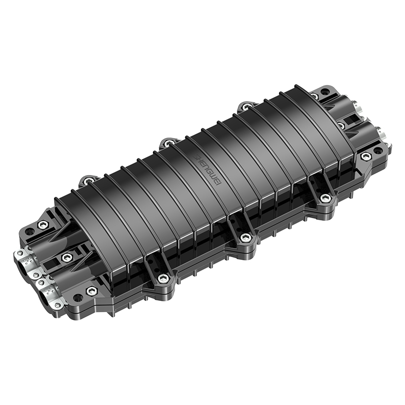
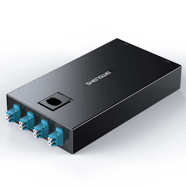
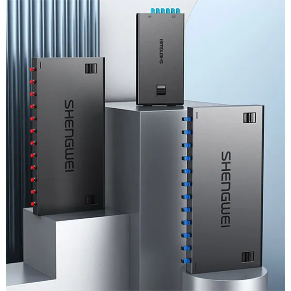
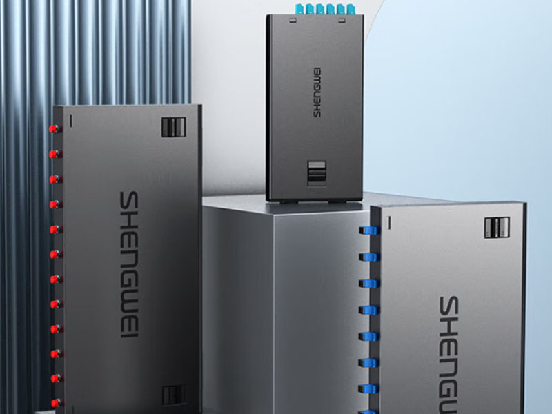
Also referred to as a fiber access terminal (FAT) or optical termination box (OTB), this enclosure serves three primary functions in an FTTH architecture: splice housing, connector adaptation, and cable strain relief. Distribution fibers arriving from a fiber distribution hub (FDH) or OLT are spliced to pigtails terminated with SC, LC, or E2000 connectors, which then mate with the rear of bulkhead adapters on a front-facing panel. Field technicians can connect or disconnect subscribers at the front panel without disturbing the splice tray — decoupling splice work from subscriber turn-up entirely.
In high-density multi-dwelling units (MDUs), the enclosure often incorporates an optical splitter directly, functioning as a combined splitter-and-termination point from a single distribution fiber. In single-family unit (SFU) deployments, a simpler pass-through unit is typically positioned at the property boundary, sometimes integrating a 1:4 or 1:8 PLC splitter for adjacent homes.
Types of Fiber Optic Terminal Box
Enclosures are classified primarily by mounting method and deployment environment. Selecting the wrong type for a given location leads to premature corrosion, difficult maintenance access, or insufficient cable management capacity.
Wall-Mount
The wall-mount variant is the most widely deployed in FTTH networks. Designed for interior walls, riser closets, basement utility rooms, or exterior building facades, these units typically accommodate 2 to 48 ports. The body is fabricated from cold-rolled steel with electrostatic powder coating for indoor use, or UV-stabilized ABS/polycarbonate for outdoor exposure. Internal bend-radius guides and splice tray holders ensure fibers maintain a minimum 30 mm bend radius throughout.
MDU installations frequently include a splitter compartment and a subscriber port compartment separated by a physical barrier — allowing the operator to lock the distribution side while leaving subscriber ports accessible to field crews.
Outdoor and Weatherproof
Outdoor enclosures are purpose-built for pole-mount, pedestal, street cabinet, or direct wall-mount applications. They must contend with temperature cycling from -40 °C to +65 °C, UV radiation, driven rain, dust, and in coastal markets, salt fog. Materials shift to UV-stabilized glass-fiber-reinforced thermoplastics that resist warping under thermal load.
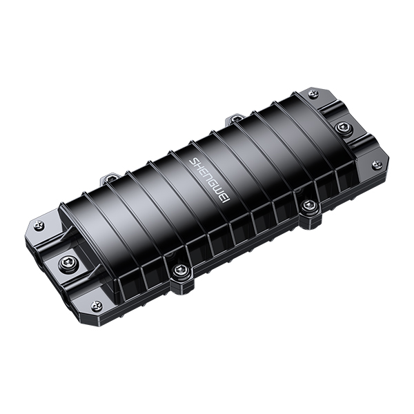
Dome or clamshell form factors with downward-facing cable entry ports use gravity to prevent water migration into the sealed interior. Cable entry is managed through PG or metric threaded glands with EPDM compression seals, and the adapter panel is often recessed behind a secondary inner cover so that opening the outer door for subscriber work does not expose the splice area to ambient humidity.
Rack-Mount
For central office, headend, or large MDU basement applications where ODFs are already present, rack-mount termination panels offer the same logical function in a standard 19-inch form factor. Port densities of 48 to 96 in 1U to 2U are common. This approach is preferred where multiple units must coexist in a single equipment room and where OLT line cards occupy adjacent rack space.
IP Ratings: IP65 vs IP68
The IP rating, defined by IEC 60529, specifies how effectively an enclosure resists dust and liquid ingress. For outdoor deployments, it is the single most important environmental specification — a mismatch between IP rating and actual site conditions is the leading cause of connector end-face contamination in the field.
| Specification | IP65 | IP68 |
|---|---|---|
| Dust Protection | Dust-tight — zero ingress | Dust-tight — zero ingress |
| Liquid Protection | Water jets, 6.3 mm nozzle, 12.5 L/min | Continuous immersion per manufacturer spec |
| Typical Depth | Not rated for submersion | 1.5 m to 3.0 m / 72 hours |
| Sealing Method | Closed-cell foam or silicone gasket | O-ring radial compression + gel-filled cable entry |
| Cable Entry | PG threaded glands with EPDM cone seal | Gel-filled compression glands or heat-shrink boot |
| Typical Material | ABS, polycarbonate, powder-coated steel | Glass-reinforced PC, UV-stabilized PBT, stainless steel |
| Cost Factor | 1.0× baseline | 1.8× to 3.0× |
| Typical Application | Exterior wall, pole with canopy | Underground handhole, flooded vault, direct-burial pedestal |
IP65 is the de facto minimum for outdoor wall-mount and pole-mount installations under partial canopy. It handles heavy rain, building wash-down, and wind-driven dust without issue.
IP68 is required where the enclosure may sit in standing water — common in tropical markets with monsoon conditions, or underground infrastructure without guaranteed drainage. For FTTH rollouts across Southeast Asia, Sub-Saharan Africa, and South Asia, IP67 or IP68 is the recommended outdoor baseline. Specifying IP65 where IP68 is required leads to seal failure within one to two wet seasons; specifying IP68 where IP65 suffices adds unnecessary cost per unit.
Installation Considerations
Choosing the right enclosure type is only half the equation. Installation quality directly determines long-term optical performance.
Mounting height and surface: For outdoor wall-mount installations, position the unit between 1.2 and 1.8 meters above grade. The mounting surface must be flat within 2 mm across the enclosure footprint — uneven surfaces induce torsional stress that deforms the gasket sealing plane and creates leak paths over time.
Cable strain relief: All cables must be secured to strain-relief clamps anchored to the enclosure frame, never to the adapter panel or splice tray. A 50 N lateral pull on an unsecured drop cable can displace an SC connector far enough to increase insertion loss by 0.5 dB or more.
Gland torque: Cable glands must be torqued to spec — typically 4 to 8 N·m for PG11 to PG16 sizes. Under-torquing voids the IP seal; over-torquing cold-flows LSZH jacket material into a pinch point that cracks after thermal cycling.
Bend radius and splice organization: Fiber routing inside the enclosure must maintain minimum bend radii (30 mm for G.657.A2, 15 mm for G.657.B3). Organize splice trays with distribution-side splices on lower layers and drop-side splices on upper layers to avoid disturbing existing splices when adding new subscribers.
Slack storage: Store a minimum of 1 meter of slack per fiber in figure-eight coils — never circular coils — to prevent twist-induced polarization mode dispersion in single-mode fiber.
Unused ports: On outdoor models, blank all unused cable entry ports with the supplied plugs. Leaving knockouts open after installation immediately voids the IP rating regardless of how well active ports are sealed.
Summary
The fiber optic terminal box is a passive component whose selection and installation quality have outsized consequences for FTTH network reliability. The right type — wall-mount for riser and indoor use, outdoor-rated for pole and facade deployment, rack-mount for central office environments — must be matched to the physical site. IP rating selection should reflect actual ground conditions: IP65 for standard outdoor exposure, IP68 for flood-prone or submerged locations. Installation discipline around strain relief, gland torque, bend radius, and port sealing collectively determines whether the enclosure remains a transparent optical path or becomes a recurring maintenance liability over the network’s 20-year service life.