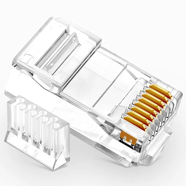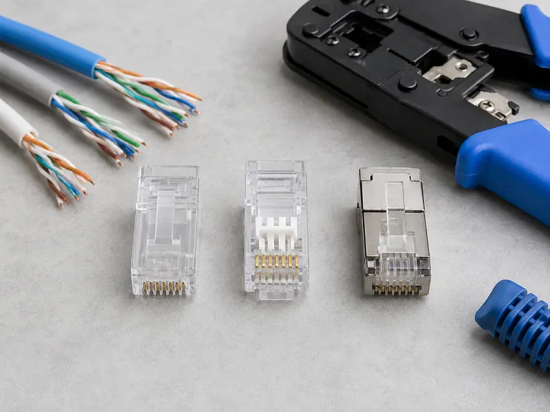
An RJ45 connector is the standard 8-position, 8-contact (8P8C) modular plug used to terminate twisted-pair Ethernet cables. It connects computers, switches, routers, IP cameras, and access points on a copper LAN — and despite looking almost identical on the outside, RJ45 connectors vary significantly in internal structure, contact design, and shielding. Selecting the wrong type is one of the most common causes of failed cable certifications, intermittent connectivity, and degraded throughput.
This guide covers the specifications and standards that matter when selecting RJ45 connectors for structured cabling, data center patching, or bulk procurement — from Cat5e through Cat6A, shielded and unshielded, with a close look at the material details that separate a reliable connector from a liability.
RJ45 Connector Types by Category: Cat5e vs Cat6 vs Cat6A
All RJ45 connectors share the same external form factor and fit the same 8P8C ports. The differences are internal — conductor hole diameter, body cavity length, pin stagger, and whether the design accommodates a cable separator. These structural differences exist because Cat5e, Cat6, and Cat6A cables use different conductor gauges and pair separation requirements.
| Specification | Cat5e | Cat6 | Cat6A |
|---|---|---|---|
| Frequency | 100 MHz | 250 MHz | 500 MHz |
| Max Data Rate | 1 Gbps | 10 Gbps (up to 55 m) | 10 Gbps (up to 100 m) |
| Conductor Gauge (typical) | 24 AWG | 23 AWG | 23–22 AWG |
| Internal Structure | Open cavity, no separator | Staggered pins, load bar common | Wide cavity, load bar required, multi-piece design |
| Pin Layout | Flat, inline | Staggered (zig-zag) | Pronounced stagger with wider spacing |
Cat5e Connectors
Cat5e RJ45 connectors have a straightforward single-piece polycarbonate body with eight flat, inline contact pins. The conductor holes are sized for 24 AWG wire, and the internal cavity does not require a load bar. These connectors are easy to terminate and work reliably at Gigabit speeds over the full 100-meter channel defined by TIA-568. For basic 1 Gbps networks where cost matters, Cat5e connectors remain adequate — but they offer no headroom for 10 Gbps upgrades.
Cat6 Connectors
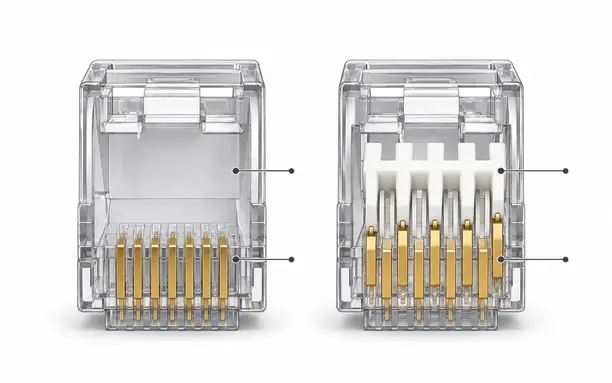
Cat6 cables use thicker 23 AWG conductors and tighter pair twists to support 250 MHz bandwidth. Cat6 RJ45 connectors accommodate this with wider conductor holes and a staggered pin layout. Many include a load bar — a small plastic insert that guides the eight wires into correct alignment before they seat against the contact pins.
Forcing Cat6 cable into a Cat5e connector is a common field error. The thicker conductors jam in the narrower holes, wires cannot seat fully against the pins, and the resulting termination introduces impedance mismatches and crosstalk — especially at 10 Gbps over shorter runs where Cat6 is theoretically capable.
Cat6A Connectors
Cat6A supports the full 10 Gbps data rate over 100 meters at 500 MHz. The cables are thicker — often 23 or 22 AWG with heavier pair shielding and a larger jacket diameter. Cat6A RJ45 connectors match this with wider internal cavities, a pronounced staggered pin layout, and multi-piece construction (typically two or three pieces with a dedicated wire guide and load bar).
These connectors demand more precision during termination. A poorly crimped Cat6A plug can fail NEXT or return loss testing even when the cable itself is within spec. For critical links, many installers prefer factory-terminated Cat6A patch cords over field-crimped connections.
Shielded vs Unshielded RJ45 Connectors
RJ45 connectors fall into two shielding categories: UTP (Unshielded Twisted Pair) and STP (Shielded Twisted Pair). The choice affects EMI protection, grounding requirements, and installation complexity.
Unshielded (UTP)
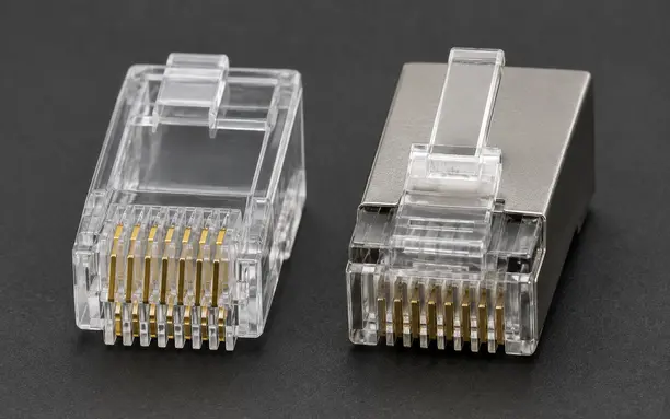
UTP connectors use an all-plastic housing with no metal shielding layer. The twisted pairs inside the cable rely on their twist rate to cancel interference. UTP connectors are less expensive, easier to terminate, and sufficient for environments with minimal EMI — offices, retail, residential, and most enterprise LANs.
Shielded (STP / FTP / S/FTP)
Shielded connectors add a metal wrap or foil layer around the body that bonds to the cable’s shielding, creating a continuous Faraday cage from end to end. They are essential in environments with heavy EMI sources — industrial facilities near motors and VFDs, hospital imaging rooms, factory floors, and dense data center cable trays running Cat6A at 10 Gbps.
One critical requirement: shielded connectors must be properly grounded at both ends. An ungrounded shield acts as an antenna, actually increasing interference rather than blocking it. Every shielded RJ45 link must connect through grounded patch panels and equipment ports to function correctly.
For outdoor and harsh-environment applications, IP67-rated waterproof RJ45 connectors extend shielding with sealed housings and gaskets — a rapidly growing segment as industrial IoT and outdoor surveillance deployments expand.
Contact Design: 2-Prong vs 3-Prong Pins
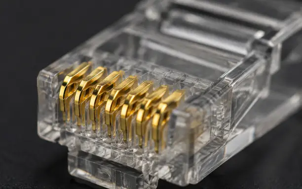
Inside every RJ45 connector, eight metal contact pins pierce through the wire insulation to make electrical contact with the copper conductor. These pins come in two designs, and the choice affects contact reliability, cable compatibility, and signal quality.
2-Prong Contacts
Two-prong pins grip the conductor from two sides. They work best with stranded wire, where the multiple fine strands compress evenly between the two contact points. On solid-core cable, 2-prong pins provide a smaller contact area, which can lead to inconsistent performance in high-frequency Cat6 and Cat6A applications.
3-Prong Contacts
Three-prong pins surround the conductor from three sides, creating a larger contact surface area. This design works reliably with both solid and stranded conductors, making it the preferred choice for mixed-cable projects. The wider contact reduces insertion loss and supports more stable high-speed transmission. For bulk purchasing, 3-prong connectors simplify inventory — one connector type covers both solid in-wall cable and stranded patch cord applications.
Gold Plating Thickness
RJ45 contact pins are typically phosphor bronze with a nickel underlayer and gold finish. The gold plating thickness — measured in micro-inches (µ”) — directly affects durability, signal integrity, and connector lifespan.
| Gold Plating | Durability | Typical Application |
|---|---|---|
| 1–3µ” (flash) | Low — single-insert applications | Consumer patch cords, temporary connections |
| 6µ” | Moderate — limited plug/unplug cycles | Standard office and residential installations |
| 30µ” | Good — repeated mating cycles, moderate humidity | Commercial structured cabling, rack patching |
| 50µ” | Highest — maximum corrosion resistance | Data centers, industrial, mission-critical links |
Connectors with flash gold may test fine initially but degrade in humid or high-traffic environments. Once the gold wears through, oxidation drives up contact resistance — causing packet loss, CRC errors, and link drops that are difficult to diagnose without re-termination. For projects requiring long-term reliability, specify a minimum of 30µ” for commercial installations and 50µ” for data center or industrial deployments.
Pass-Through vs Standard RJ45 Connectors
RJ45 plugs come in two termination styles that affect the installation workflow but not electrical performance.
Standard (non-pass-through) plugs require wires to be cut to a precise length before insertion. They bottom out against the front wall of the connector and are fully enclosed after crimping. This design is the norm for factory-terminated patch cords and preferred by experienced installers.
Pass-through plugs allow wires to feed completely through the connector body and exit from the front. The installer can visually verify wire order before crimping, and a pass-through crimper cuts the excess wire flush. This reduces termination errors and speeds up field work, but requires a dedicated crimping tool and generates more waste per termination.
Both styles deliver equivalent performance when properly terminated. The choice is workflow preference and installer experience level.
Solid vs Stranded Cable: Matching the Right Connector
Mismatching connectors and conductor types is a frequent source of unreliable terminations.
Solid conductor cable uses a single thick copper core per wire. It maintains consistent impedance over distance and is the standard for permanent in-wall runs. Best practice is to terminate solid cable to keystone jacks or patch panels using punch-down (IDC) connections rather than field-crimped RJ45 plugs.
Stranded conductor cable uses multiple fine copper strands per wire. It handles repeated bending without breaking and is used for patch cords and equipment jumpers. RJ45 modular plugs are primarily designed for stranded cable.
If a project requires crimping RJ45 plugs onto solid cable, use connectors explicitly rated for solid wire — or 3-prong contact plugs that accommodate both types. Using a stranded-only connector on solid cable results in poor pin contact and intermittent failures.
Key Specs to Check When Ordering in Bulk
For procurement managers and system integrators sourcing RJ45 connectors in volume, verify these specifications before placing an order:
- Category rating — Match the connector to the cable (Cat5e, Cat6, or Cat6A). Never downgrade.
- Shielding type — UTP for standard environments; STP/FTP for EMI-heavy or high-density installations.
- Contact design — 2-prong for stranded-only; 3-prong for mixed solid/stranded or higher performance needs.
- Gold plating — Minimum 6µ” for commercial; 30µ” for enterprise; 50µ” for data center and industrial.
- Conductor compatibility — Solid, stranded, or universal. Verify AWG range (typically 23–26 AWG).
- Plug style — Standard or pass-through, based on your team’s tooling.
- Certifications — UL listed, RoHS compliant. Request Fluke test reports for bulk orders.
- Housing material — High-grade polycarbonate (PC) for latch durability and long service life.
Frequently Asked Questions
Are Cat5e and Cat6 RJ45 connectors interchangeable?
They fit the same ports, but they are not interchangeable for reliable performance. Cat6 cables have thicker 23 AWG conductors that do not seat properly in Cat5e connector cavities. Always match the connector category to the cable category.
What gold plating thickness should I specify?
For general office use, 6µ” is sufficient. Commercial structured cabling should specify 30µ” for a good balance of cost and durability. Data centers and industrial environments should use 50µ” for maximum corrosion resistance.
Do I need shielded RJ45 connectors?
Only in environments with significant electromagnetic interference — near industrial machinery, medical imaging equipment, or in dense cable trays running 10 Gbps Cat6A. Standard office and residential settings work well with unshielded (UTP) connectors.
What is the difference between 2-prong and 3-prong contacts?
Two-prong pins grip the conductor from two sides and are optimized for stranded wire. Three-prong pins contact from three sides, providing a larger contact area that works with both solid and stranded conductors — more versatile for mixed-cable projects.
Can I crimp RJ45 plugs onto solid-core cable?
Yes, with connectors rated for solid conductors. However, best practice for permanent installations is to terminate solid cable to keystone jacks or patch panels using punch-down connections, and use factory-made patch cords for flexible equipment links.
Need Help Selecting the Right RJ45 Connector?
If you have questions about connector specifications, category matching, or bulk order requirements, our engineering team can help you find the right fit for your project. Reach out and we will respond within 24 hours.