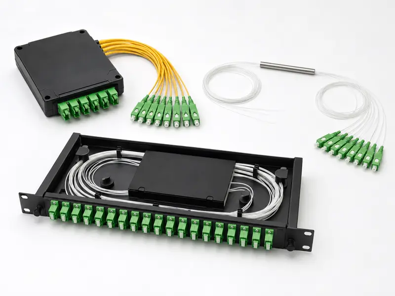
An optical splitter takes a single fiber signal from an OLT and divides it among multiple subscribers — no power supply, no active electronics, no recurring maintenance. It is the branching point that makes passive optical networks economically viable.
But choosing the wrong splitter — wrong technology, wrong split ratio, wrong packaging — leads to uneven power distribution, wasted optical budget, or a network that cannot scale. This guide walks through the two splitter technologies (PLC and FBT), split ratio planning with real link budget math, packaging selection, and deployment architecture. The perspective here comes from the manufacturing and field-support side: what we see go wrong, what questions come up on spec sheets, and what actually matters versus what gets over-specified.
What an Optical Splitter Actually Does
An optical splitter — also called a fiber optic splitter or beam splitter — is a passive component that divides one input optical signal into two or more output signals. In a PON architecture, it sits between the central office and the subscriber terminals (ONUs), branching one feeder fiber into many distribution fibers.
Because splitters are entirely passive, they introduce no active failure points and consume no power. A single GPON OLT port can serve up to 128 subscribers through one or more stages of splitting. In practice, most operators cap at 32 or 64 — not because of the splitter, but because of the optical power budget and the bandwidth each subscriber actually needs.
PLC vs FBT: Two Technologies, Very Different Trade-Offs
Every optical splitter uses one of two manufacturing approaches. Understanding the difference is not academic — it directly determines cost, scalability, and which deployment scenarios each type can handle.
FBT (Fused Biconical Taper)
An FBT splitter is made by fusing two or more bare fibers together under heat while stretching them into a tapered shape. The fused region creates a coupling zone where optical power transfers between fibers. The process is mature and inexpensive for small split counts.
The limitation is uniformity. At 1×2, an FBT splitter can achieve a nearly even 50/50 split. But building higher ratios requires cascading multiple 1×2 stages — a 1×8 needs three cascading levels, and each stage introduces its own tolerance variation. By the time you reach 1×16 or 1×32 through cascading, the accumulated non-uniformity becomes a real problem: some output ports may receive 1.5–2 dB more power than others. That difference matters when you are already running close to your optical budget limit.
PLC (Planar Lightwave Circuit)
A PLC splitter uses photolithographic etching on a silica-on-silicon waveguide chip to create precise branching circuits in a single step. This semiconductor-based approach produces highly uniform output across all ports — even at 1×64, the port-to-port uniformity stays within 1.5 dB. The chip operates across the full single-mode window (1260–1650 nm), covering GPON, EPON, XGS-PON, and CATV overlay wavelengths simultaneously.
A common misconception is that PLC splitters are significantly more expensive. That was true a decade ago. Today, the per-port cost of a PLC 1×8 is comparable to a cascaded FBT 1×8 — and at 1×16 and above, PLC is cheaper because you avoid the labor and enclosure space of cascading multiple FBT stages.
Side-by-Side Comparison
| Parameter | FBT Splitter | PLC Splitter |
|---|---|---|
| Manufacturing process | Fiber fusion & tapering | Photolithography on silica waveguide |
| Practical split ratios | 1×2, 1×4, 2×2 (cascaded to 1×8 max) | 1×2 to 1×64, 2×2 to 2×64 |
| Wavelength range | Dual-window (1310/1550 nm) | Full band (1260–1650 nm) |
| Output uniformity | Moderate — degrades with cascading | Excellent — ≤1.5 dB at 1×32 |
| Operating temperature | −40 °C to +85 °C | −40 °C to +85 °C |
| Per-port cost at 1×2 | Lower | Slightly higher |
| Per-port cost at 1×16+ | Higher (cascading overhead) | Lower |
| Best use case | CATV taps, monitoring, simple 1×2 splits | FTTH / GPON / EPON / XGS-PON mass deployment |
The practical rule: use PLC for any ratio above 1×4, or whenever you need full-band wavelength coverage. Use FBT only for simple 1×2 or 2×2 splits where the lower per-unit cost matters and you will never need to scale beyond that ratio.
Split Ratio Planning: The Math That Actually Matters
Every split introduces insertion loss — the reduction in optical power at each output port. The table below shows maximum insertion loss values for PLC splitters that comply with Telcordia GR-1209-CORE:
| Split Ratio | Max Insertion Loss (dB) | Typical Deployment |
|---|---|---|
| 1×2 | 4.0 | Secondary split, monitoring tap |
| 1×4 | 7.4 | Small MDU, rural cluster |
| 1×8 | 10.7 | Mid-density residential |
| 1×16 | 13.8 | Urban FTTH distribution |
| 1×32 | 17.5 | High-density GPON |
| 1×64 | 21.5 | Maximum density, short-reach PON |
A Real Link Budget Example
One question we get frequently from ISP procurement teams: “Can I use 1×32 on a 20 km span with Class B+ OLT?” Here is the math:
Fiber attenuation: 20 km × 0.35 dB/km = 7.0 dB
Splitter insertion loss (1×32 PLC): 17.5 dB
Connector pairs (4 × 0.5 dB): 2.0 dB
Fusion splices (3 × 0.1 dB): 0.3 dB
Total: 26.8 dB — within the 28 dB Class B+ budget, with 1.2 dB margin.
That 1.2 dB margin is tight. In real deployments, connector quality varies, fiber bends add micro-loss, and splitter aging can push insertion loss up by 0.2–0.3 dB over ten years. If you are planning for a 20-year service life, we recommend targeting at least 2 dB of margin. For this scenario, that means either shortening the span, upgrading to a Class C+ OLT (32 dB budget), or dropping to 1×16.
This is one of the most common over-specification mistakes we see: operators pick 1×32 because the datasheet says it fits, without accounting for real-world margin erosion. The splitter loss number on a datasheet is a maximum — your actual units will likely be 0.5–1.0 dB lower — but planning to maximum is the only safe approach.
Packaging: Match the Housing to the Installation
The same PLC chip can be packaged in several different housings. The choice depends on where the splitter will be installed and how the fibers are terminated.
Bare Fiber / Steel Tube
The PLC chip sits in a stainless steel tube with bare fiber pigtails. This is the smallest form factor and is designed for environments where fibers are fusion-spliced — typically inside splice closures, distribution boxes, or terminal boxes. No connectors, no adapter panels — just raw fiber ready for the splicer.
ABS Box Type
The chip is housed in a compact ABS plastic enclosure with pre-connectorized pigtails — usually SC/APC for FTTH. This is the most popular form factor globally because it eliminates splicing in the field. A technician plugs the input and output fibers directly into the adapters. ABS box splitters fit inside distribution boxes, wall-mount cabinets, and outdoor closures.
One detail worth noting: the pigtail fiber type matters. For FTTH environments, insist on G.657.A2 bend-insensitive fiber in the pigtails, not standard G.652.D. The tight bend radii inside compact enclosures will cause measurable loss with standard fiber — sometimes 0.5 dB or more per bend, which eats directly into your link budget.
LGX Cassette / Insert Type
The splitter is built into a standard LGX-compatible cassette that slides into a rack shelf or wall enclosure. Input and output ports appear as adapters on the front panel. This format is the default for central offices, headends, and ODFs where splitters need to be managed, labeled, and swapped without disrupting adjacent circuits.
Rackmount (1U / 2U)
A 19-inch chassis holds one or more splitter cassettes. Standard for central offices and data center meet-me rooms where dozens of PON ports terminate. A 1U chassis typically holds up to 2×32 or 1×64 configurations with full front-panel access.
Which Package for Which Location?
| Installation Point | Recommended Package | Why |
|---|---|---|
| Central office / ODF | LGX cassette or rackmount | Managed environment, needs hot-swap capability |
| Outdoor cabinet / pedestal | ABS box inside splice closure | Weatherproof enclosure, plug-and-play |
| Building basement / riser | ABS box inside distribution box | Compact, pre-connectorized |
| Floor distribution point | Bare fiber in terminal box | Space-constrained, spliced connections |
Single-Stage vs Two-Stage Splitting: A Deployment Decision
FTTH networks use either a single splitter or two cascaded splitters to reach the target split ratio. This is not a purely technical decision — it is an economic and operational one.
Single-Stage
One 1×32 or 1×64 splitter at a single distribution point. Simpler to plan, fewer components to manage, lower total insertion loss (one splitter instead of two in series). Works well in concentrated residential areas where most subscribers are within a short radius of the distribution hub.
Two-Stage (Cascaded)
A first-level splitter (e.g., 1×4) near the feeder route and second-level splitters (e.g., 1×8) closer to subscriber clusters. Combined ratio: 1×4 × 1×8 = 1×32. The advantage is capital efficiency — you only deploy second-level splitters when subscribers are ready, which matters enormously in greenfield rollouts where take rates start at 20–30% and build over years.
The trade-off: two-stage splitting adds insertion loss from two splitters in series plus additional connector or splice losses at the intermediate point. A cascaded 1×4 + 1×8 has a combined insertion loss of roughly 7.4 + 10.7 = 18.1 dB, compared to 17.5 dB for a single 1×32. That 0.6 dB difference is small but not negligible when you are already running at tight margins.
A pattern we see in successful rollouts: operators use two-stage for greenfield (new build, uncertain demand) and single-stage for brownfield or MDU retrofits (known subscriber count, short distances).
Three Specification Mistakes to Avoid
These come up repeatedly in RFQs and project specs we review:
1. Specifying FBT at 1×16 or higher. Some procurement templates still list FBT as an option for 1×16 or 1×32 because FBT was once cheaper. At these ratios, FBT requires multiple cascading stages, which increases size, cost, and — most critically — uniformity problems. For anything above 1×8, PLC is the correct technology.
2. Ignoring connector return loss in PON applications. PON networks require SC/APC (angled physical contact) connectors, not SC/UPC. APC connectors have a return loss of ≥60 dB, versus ~50 dB for UPC. The difference prevents back-reflected light from interfering with the OLT’s burst-mode receiver. We still see RFQs that specify SC/UPC for PON splitters — this is a compatibility issue that will cause intermittent errors under load.
3. Under-specifying temperature range for outdoor deployment. A splitter installed in an outdoor splice closure in a tropical or desert climate needs a rated range of at least −40 °C to +85 °C. Some lower-cost splitters are only rated to +70 °C. Inside a black splice closure exposed to direct sun, the internal temperature can exceed 70 °C easily. Verify the rated range on the test report, not just the datasheet front page.
Frequently Asked Questions
What is the difference between an optical splitter and a WDM?
A splitter divides one signal equally across all output ports regardless of wavelength. A WDM (wavelength division multiplexer) separates or combines signals by wavelength — each port carries a different wavelength. In PON networks, splitters distribute the same downstream signal to all ONUs, while WDM devices combine 1310 nm upstream, 1490 nm downstream, and 1550 nm video overlay onto a single fiber.
Can I cascade two PLC splitters?
Yes — cascading is standard in two-stage FTTH architectures. A 1×4 feeding four 1×8 splitters gives a total 1×32 split. The combined insertion loss is the sum of both stages plus connector losses at the junction. Ensure the total stays within your OLT’s power budget.
How long does a PLC splitter last?
PLC splitters are passive — no moving parts, no electronics. Under normal conditions within the rated temperature range, they are designed for 20+ years of service. Telcordia GR-1221-CORE qualification includes 2,000-hour damp heat at 85 °C / 85% RH, 500 thermal cycles between −40 °C and +85 °C, and mechanical shock and vibration testing.
What split ratio should I use for GPON?
Most GPON deployments use 1×32 (Class B+ OLT, up to 20 km) or 1×16 (longer spans or higher margin). For dense urban MDUs with fiber runs under 5 km, 1×64 maximizes port utilization. The GPON standard supports up to 1×128, but this is rarely deployed because the optical budget leaves almost no margin at that ratio.
Does an optical splitter need power?
No. Splitters are entirely passive — no power, no cooling, no software. This is a core advantage of PON architecture: the entire outside plant between OLT and ONU contains zero active equipment.